I'm building the G935s from a bunch of blocks that are individually shaped, joined together and then shaped some more. To do that I need to plan out what blocks I'll need using the CAD geometry as a guide. Overall symmetry is necessary to look right so a method of alignment is needed. The jig plates are done and now the dowel pins will be added to use as the positioning guides for the entire construction.
Overall symmetry is necessary to look right so a method of alignment is needed. The jig plates are ready and now the dowel pins will be added to use as the positioning guides for the entire construction. Once the dowel pin locations are transferred and drilled into the main body block I can repeatedly put the growing construction of blocks back on the jig to ensure continuing symmetry. The key to that is that each centerline block must have an indelible line to match the scribed jig plate centerline. This method worked well on the 935 AP.
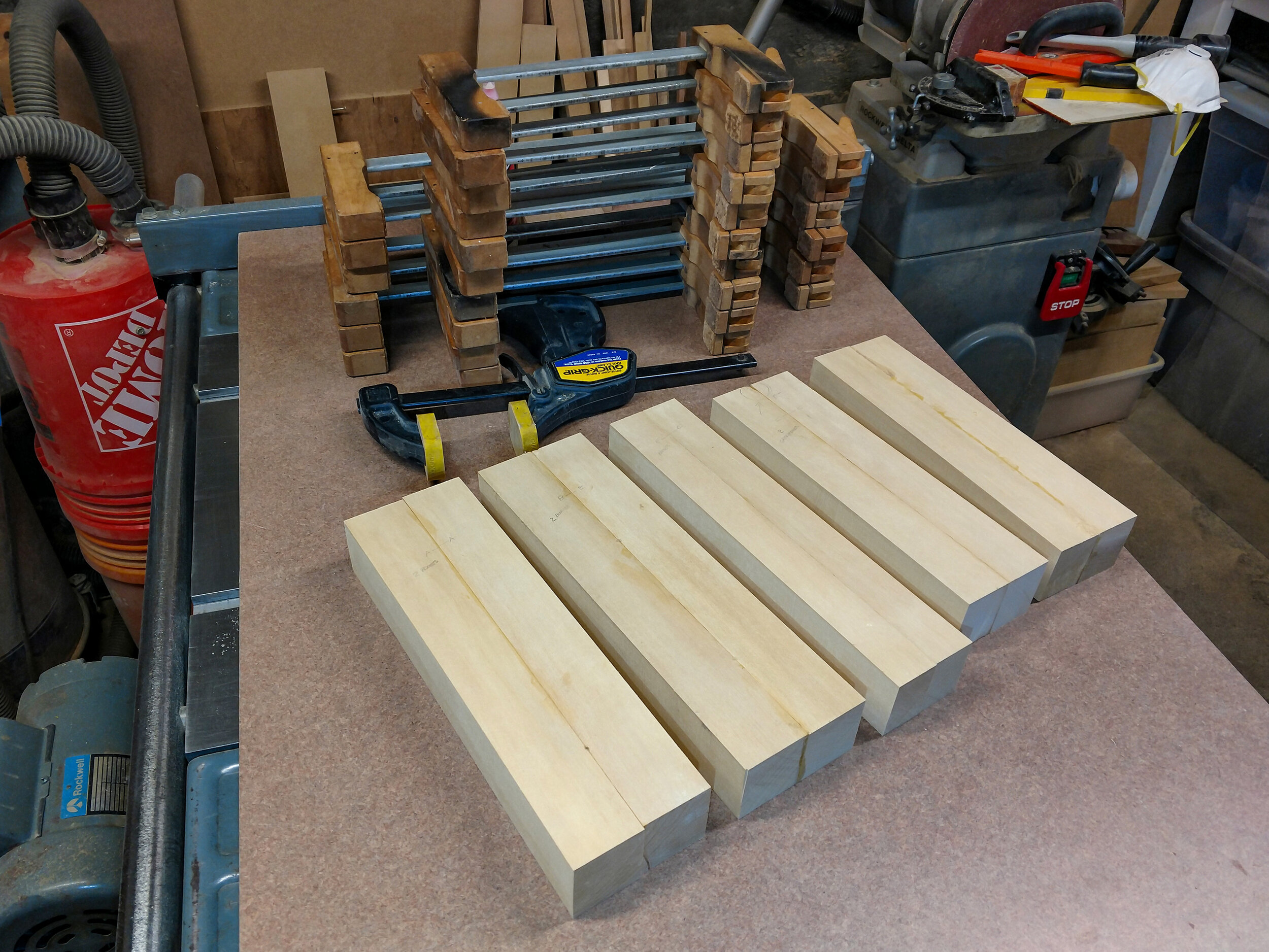
The main jelutong blocks (one is in the upper right) have been planed and are ready for divvying up into individual piece. Planning before cutting should save some extra work.
The main blocks are split on the bandsaw. One of each pair of split blocks is reversed to butterfly the grain and then they're glued up. The glue line gives the all-important construction centerline.
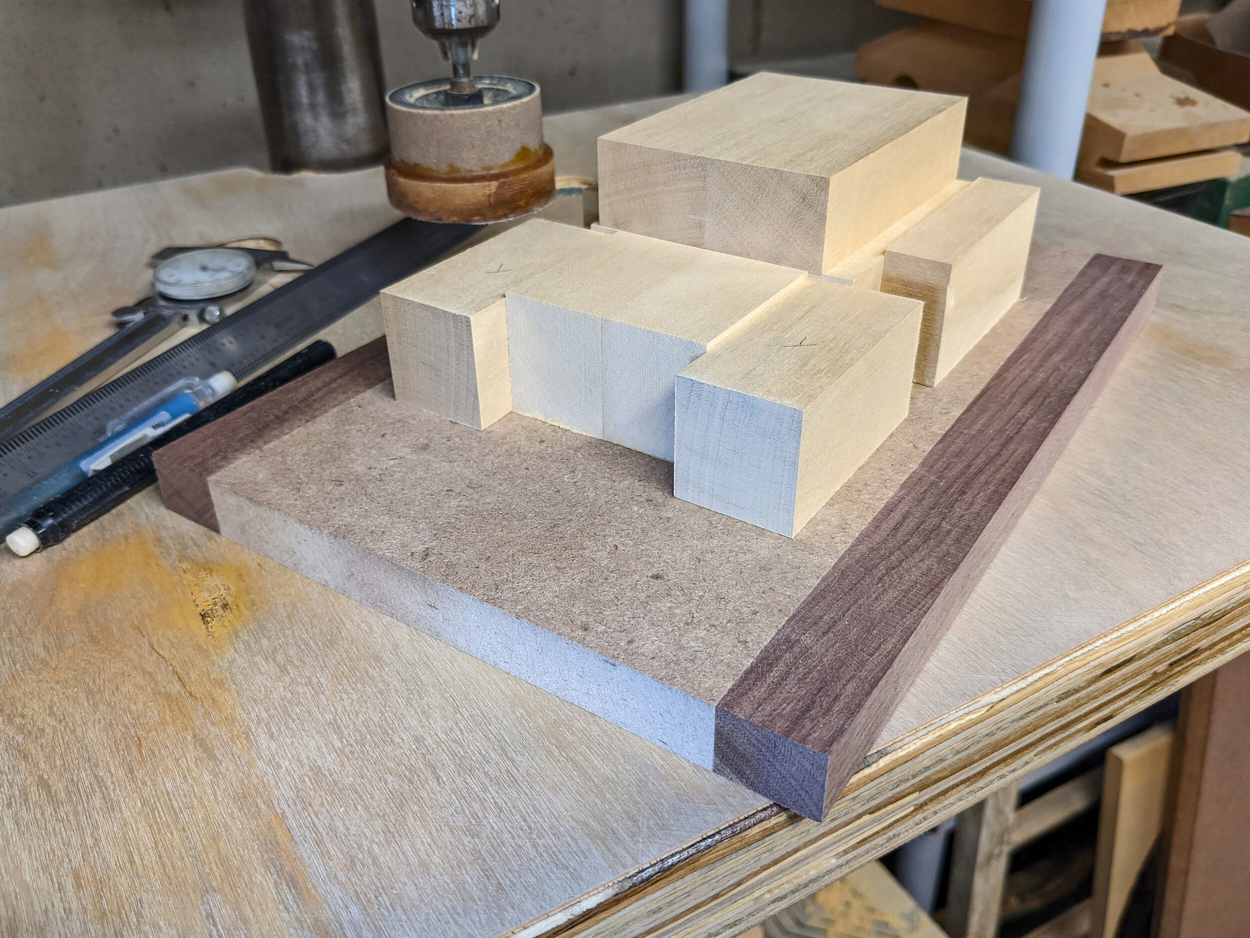
With the main blocks gathered together for the first time it looks more like a tank than a 935. That will gradually change.
Once the holes for the jig plate press-fit dowel pins have been marked and drilled, locating pins (the pointy bits) are put in. Then the block can be carefully positioned over them using the front face and the centerline. A gentle tap and the exact locations are transferred to the block.
The final result is that the main body block is centered on the jig plate. The ruler is a tiny tick off center - blame the photographer (me).
Next up – 004 – Engine Bay - The main body block is a bit like the monocoque in a race car. It's load bearing and everything else is built off it. In order to create space for the engine bay and still define the rear fender profile, a small extension piece is needed.
For more of the story click on any of the following links:
012 - 2nd Skins Layer-Splitters
007 - 3D Printing the Engine Bay
- You’re here in the list.


