Porsche G935 - 004 - Engine Bay


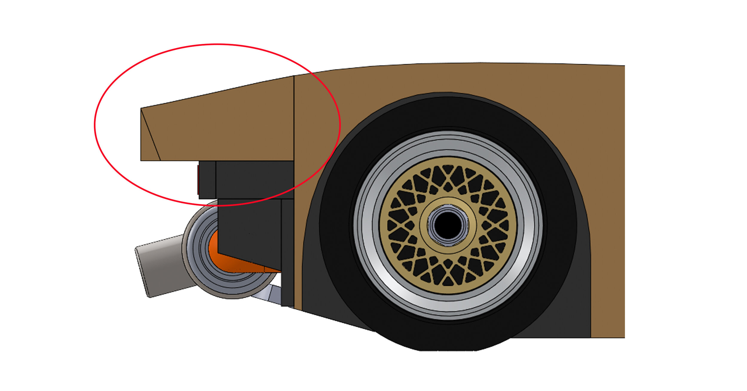
Experience from making the 935 Artist's Proof led me to figure out a way to avoid having to hog out the entire engine bay with chisels. CAD preparation let me develop a way to surround the space instead.

The main body block is a bit like the monocoque in a race car. It's load bearing and everything else is built off of it. It runs from the base of the windshield to the rear fender edge. In order to leave space for the engine bay and still create the side profile, a small extension piece is needed.

002 12 c1.jpg

This is the extension from the main body that will carry the main body profile through to the rear fender edges.

003 10.jpg

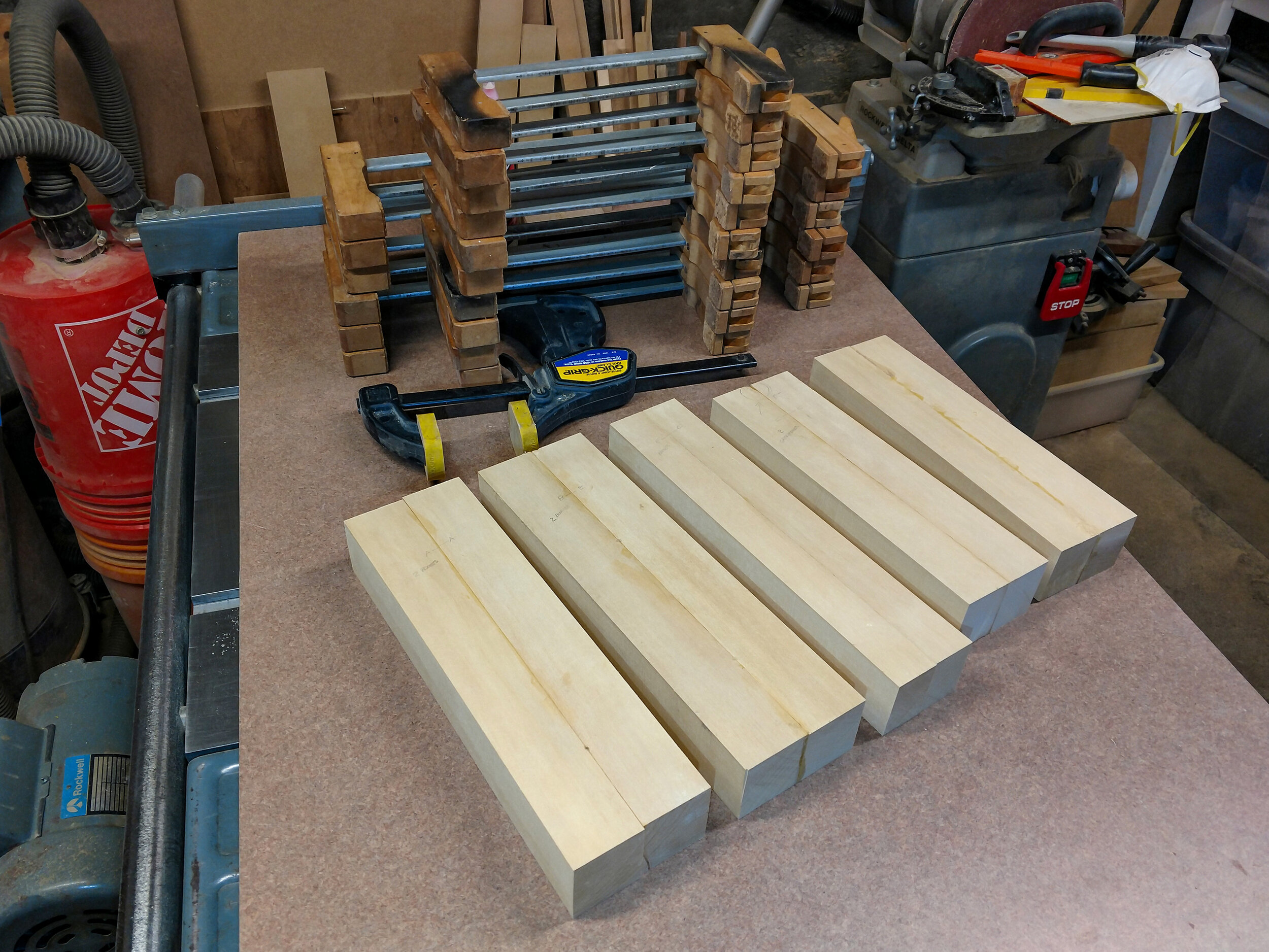
Previously glued up butterfly stock was rough cut to thickness. The measurement gage block allows faster bandsaw set ups.

004 10 c1.jpg

The extensions have been thickness sanded and cut to nominal size, ready to be glued in place.

006 10.jpg

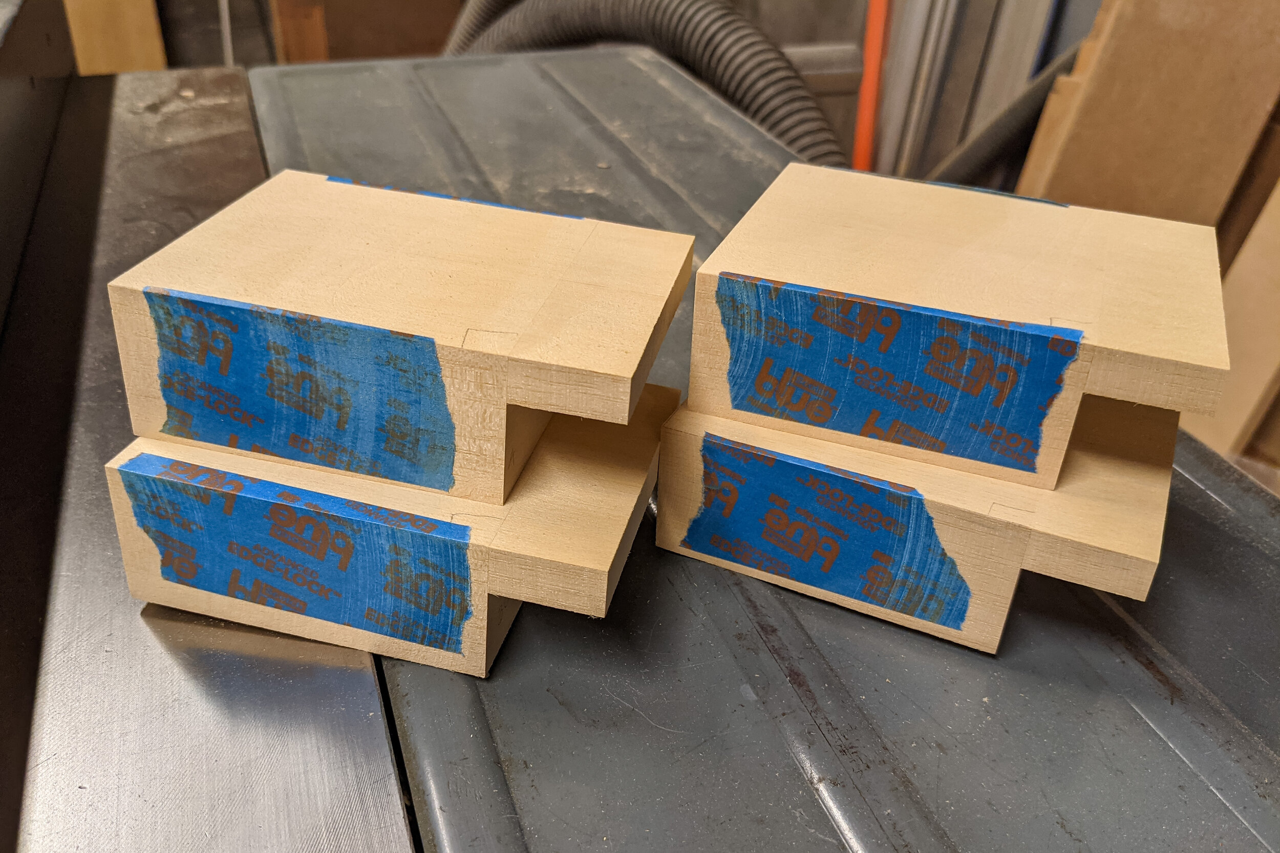
All glued up and sanding has been started. Since squareness is important, the blue tape allows me to do my preliminary sanding quite close to finished dimensions without taking off any needed material.

Careful incremental sanding gave indications on the tape that showed it was close enough to be finished sanded by hand.

007 12.jpg

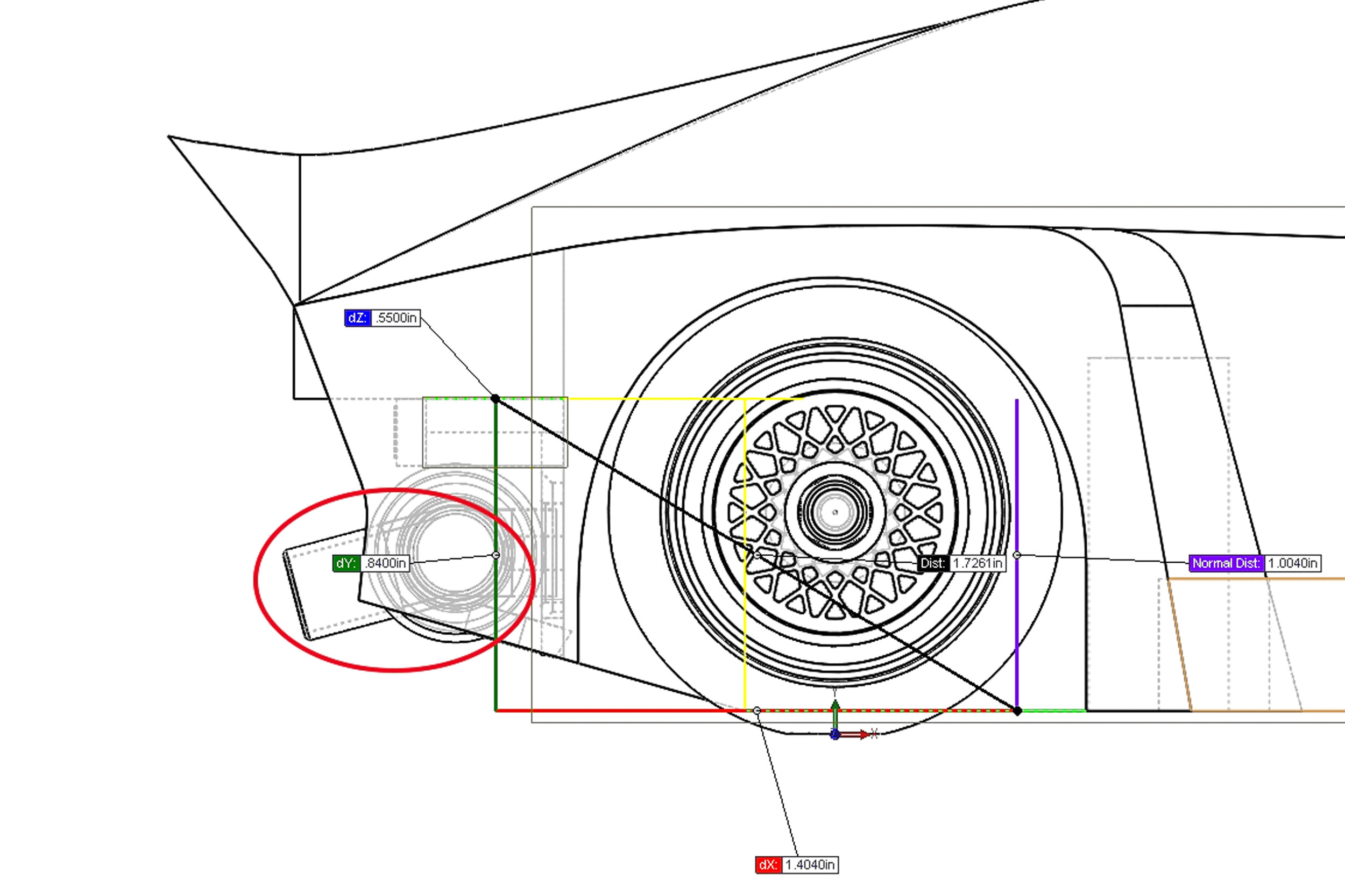
Arghhh! CAD and reality did not match. My mind was elsewhere when I determined the position of the extensions. The good part is that I could add material in a more controlled way than I could have removed it.

New extension gap-fillers were made and then it was back to gluing and sanding. Measure as many times as it takes and cut once.

Once the correct dimensions were reached, I made and applied the side profile templates and then carefully added the main side profile.

Next up - 005 - Greenhouse - The Porsche G935 greenhouse is one of the most important pieces to be added since it determines the position and shape of so many other parts.


Porsche G935 - 003 - Building Blocks


I'm building the G935s from a bunch of blocks that are individually shaped, joined together and then shaped some more. To do that I need to plan out what blocks I'll need using the CAD geometry as a guide. Overall symmetry is necessary to look right so a method of alignment is needed. The jig plates are done and now the dowel pins will be added to use as the positioning guides for the entire construction.

Overall symmetry is necessary to look right so a method of alignment is needed. The jig plates are ready and now the dowel pins will be added to use as the positioning guides for the entire construction. Once the dowel pin locations are transferred and drilled into the main body block I can repeatedly put the growing construction of blocks back on the jig to ensure continuing symmetry. The key to that is that each centerline block must have an indelible line to match the scribed jig plate centerline. This method worked well on the 935 AP.

001 10.jpg

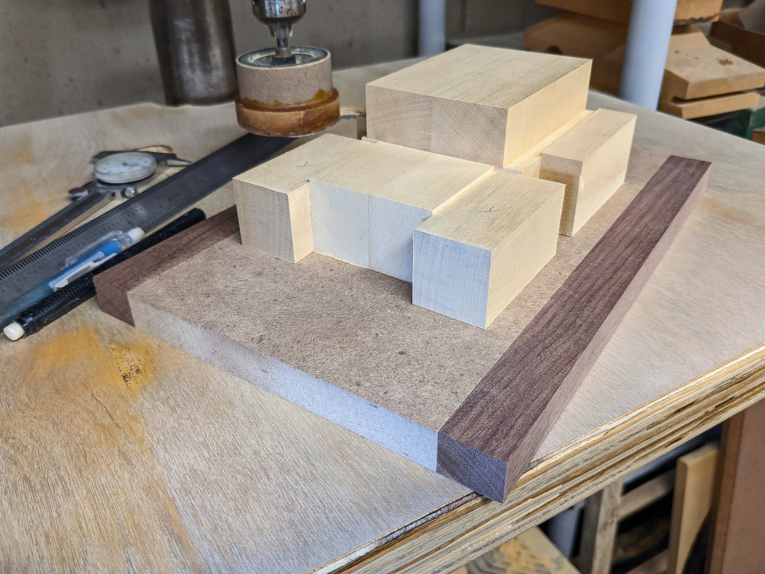
The main jelutong blocks (one is in the upper right) have been planed and are ready for divvying up into individual piece. Planning before cutting should save some extra work.

003 10.jpg

The main blocks are split on the bandsaw. One of each pair of split blocks is reversed to butterfly the grain and then they're glued up. The glue line gives the all-important construction centerline.

005 10.jpg

With the main blocks gathered together for the first time it looks more like a tank than a 935. That will gradually change.

007 10.jpg

Once the holes for the jig plate press-fit dowel pins have been marked and drilled, locating pins (the pointy bits) are put in. Then the block can be carefully positioned over them using the front face and the centerline. A gentle tap and the exact locations are transferred to the block.

008 10.jpg

The final result is that the main body block is centered on the jig plate. The ruler is a tiny tick off center - blame the photographer (me).

Next up – 004 – Engine Bay - The main body block is a bit like the monocoque in a race car. It's load bearing and everything else is built off it. In order to create space for the engine bay and still define the rear fender profile, a small extension piece is needed.


Porsche G935 - 002 - Concept Revision


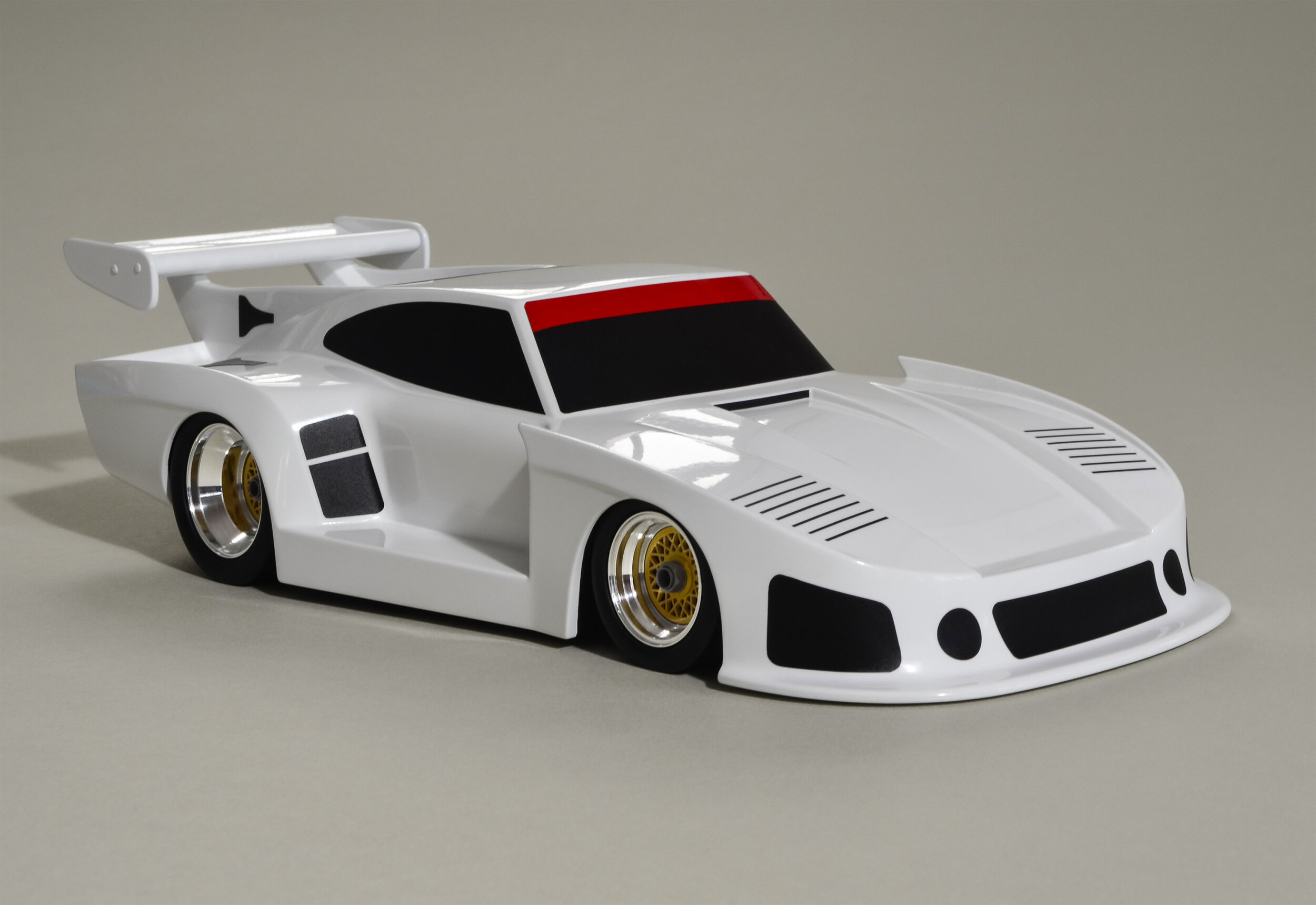
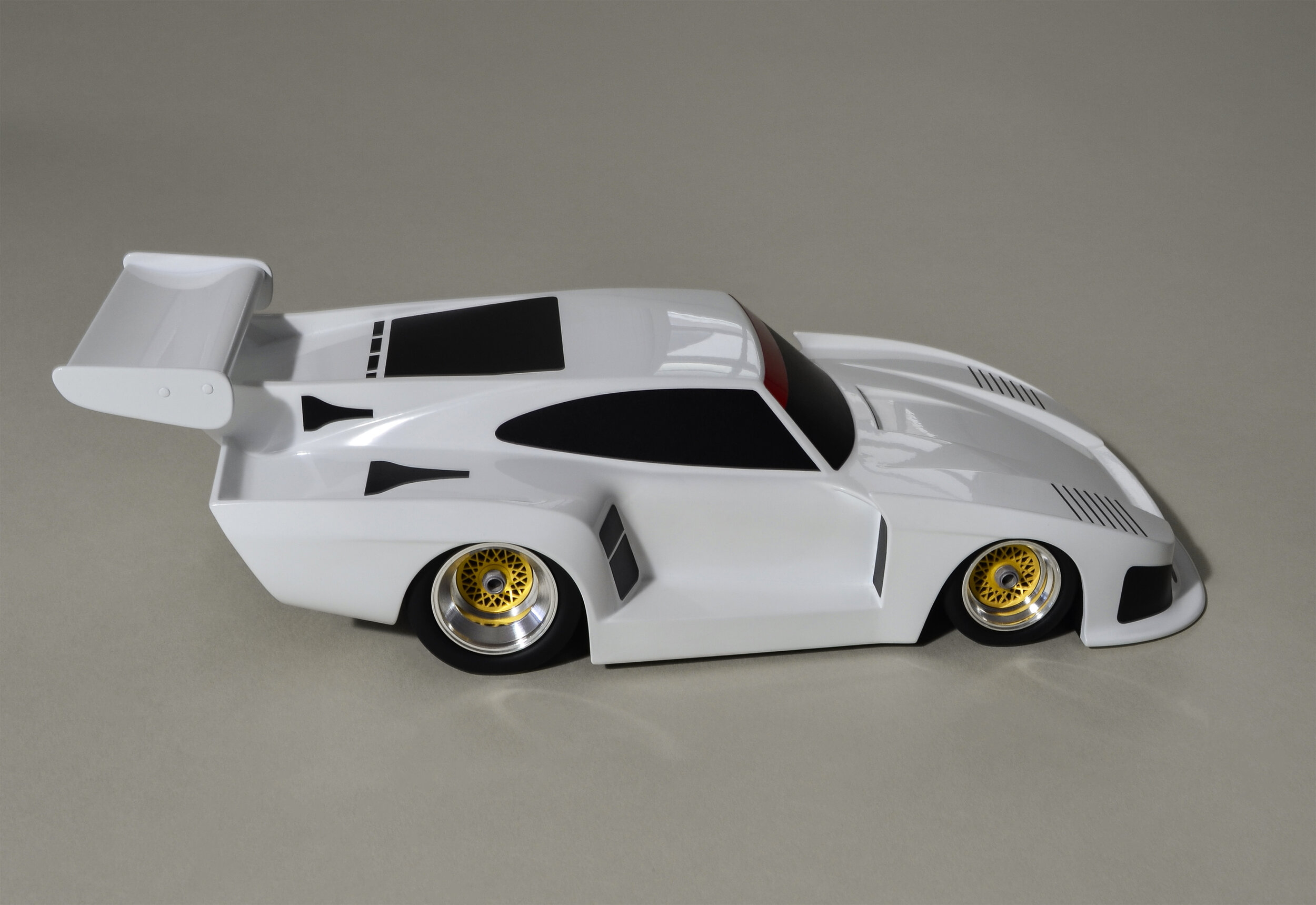
Here's how all three versions compare.

Here's how all three versions compare.

It has been awhile. Did some fantastic traveling to see family. Then I've been dealing with Lyme disease and having to lay low for a good bit. Long term effects remain to be seen. But I've still made some progress in the shop.

The biggest advance has been a significant change in the overall character of the G935s for my sons. I finally realized that I was simply making incremental changes to the AP version and not really getting back to the original Co-Hog Toys’ goal of creating a smile with every glance.

So, they've been modified to riff on the early stocky, wide, pugnacious Co-Hog proportions. Wheels and tires will be close to the AP version because the play of detailed wheels on a properly stanced, but highly simplified body is still the key.

 Let me know what you think.

Since I learned a few things from building the AP version, I'm spending more time in CAD to refine my building process up front rather than so much building and fixing all along.

Since I learned a few things from building the AP version, I'm spending more time in CAD to refine my building process up front rather than so much building and fixing all along.

006.jpg

Finally bought a new drill press thickness planer to replace the 35 year old original. Sharpening the old rakers is just not working out and I can't figure out why not - yet. They're turned inward in the picture to protect the cutting edges.

All of the jig plates and main blocks for four G935s are cut and planed flat.

All of the jig plates and main body blocks for four G935s are cut and planed flat.

Next up - 003 – Building Blocks - The Porsche G935s are started by building up a variety of blocks that are individually shaped and then joined. More blocks are added, and more shaping is done to gradually define the overall profiles.  


Porsche G935 - 001- Starting Point


The next project to work on is three Porsche G935's, one for each of my sons. Each will be slightly different to suit their preferences. One will definitely be an art car with unique graphics to be designed by the recipient. It's a great chance to have some fun and stretch the creativity envelope a wee bit.

The 'G935' nomenclature is my way of keeping the changes separate from the 935 Co-Hog edition specifications. The improvements that I like will be incorporated in the first Co-Hog edition, but there will only be these three G935's.

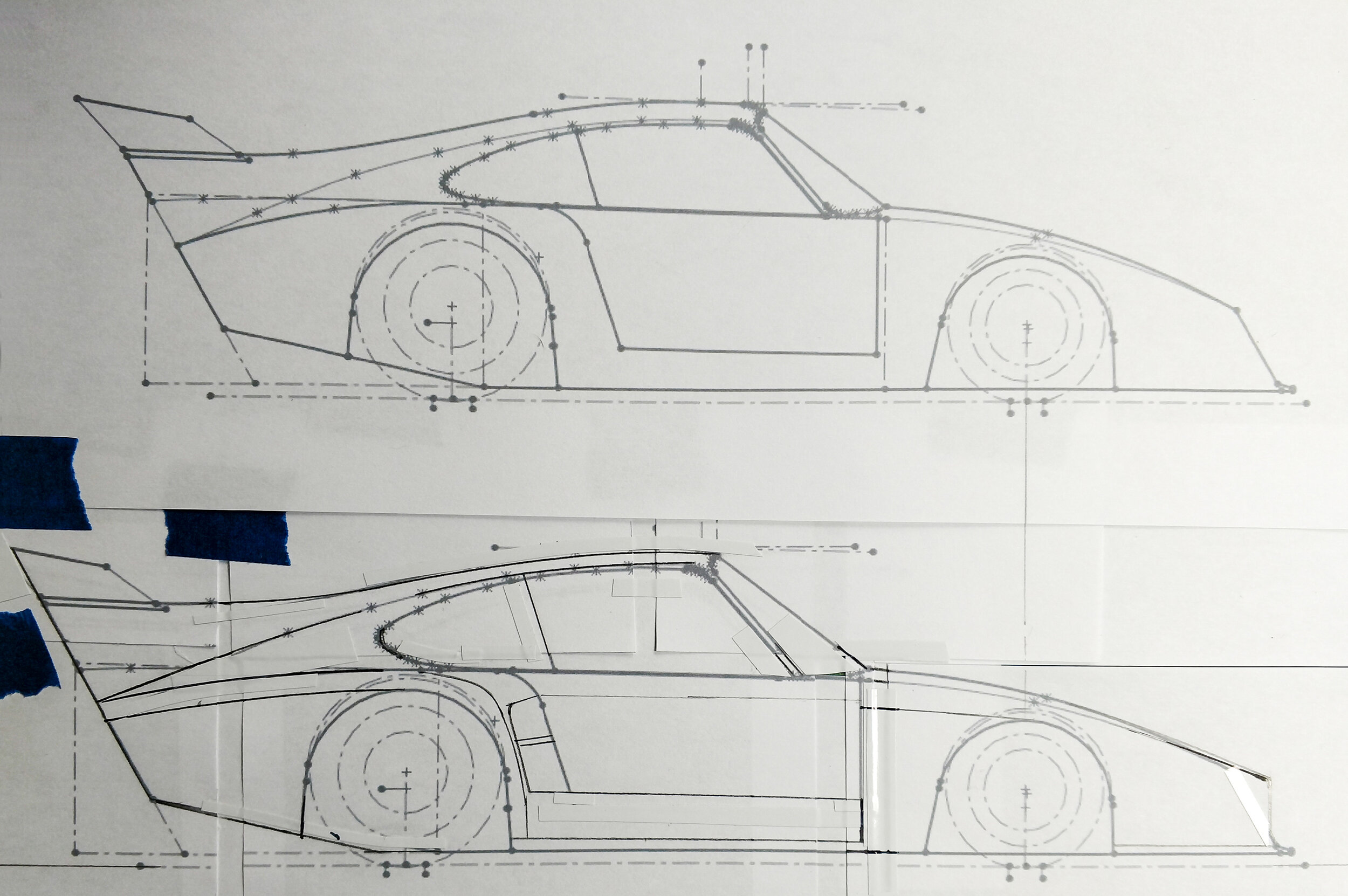
At the top is the working drawing for the recently completed Artist's Proof (AP).

Using an X-Acto knife to separate sections, clear tape and white vinyl bits for masking, I've started to try out the intended changes. Pencil and automotive sweeps let me make adjustments. I scan promising versions into Photoshop files for further changes. This cut and paste method allows me to quickly try many subtle variations.

Wheel center and tire outer diameters will stay the same but the profiles of both will change a bit as will the engines.

As with the AP, the G935s will have a jig plate to allow for continuous comparison during the builds. This allows repeatable positioning for adjustments and helps greatly with overall symmetry.

All of the pieces in a pile with one version of the working drawing.

Next up - 002 – Concept Revision – There has been a significant change in the overall character of the G935s for my sons. I finally realized that I wasn’t really getting back to the original Co-Hog Toys’ goal of creating a smile with every glance. So, they've been modified to riff on the early stocky, wide, pugnacious Co-Hog proportions.


Porsche 935 AP Walkaround


Walking around a race car makes a huge difference in understanding its stance, lines and forms. I’m hoping this quick video will also help you get a better feel for the Porsche 935 Co-Hog Artist’s Proof version.

Porsche 935 Artist’s Proof Completed


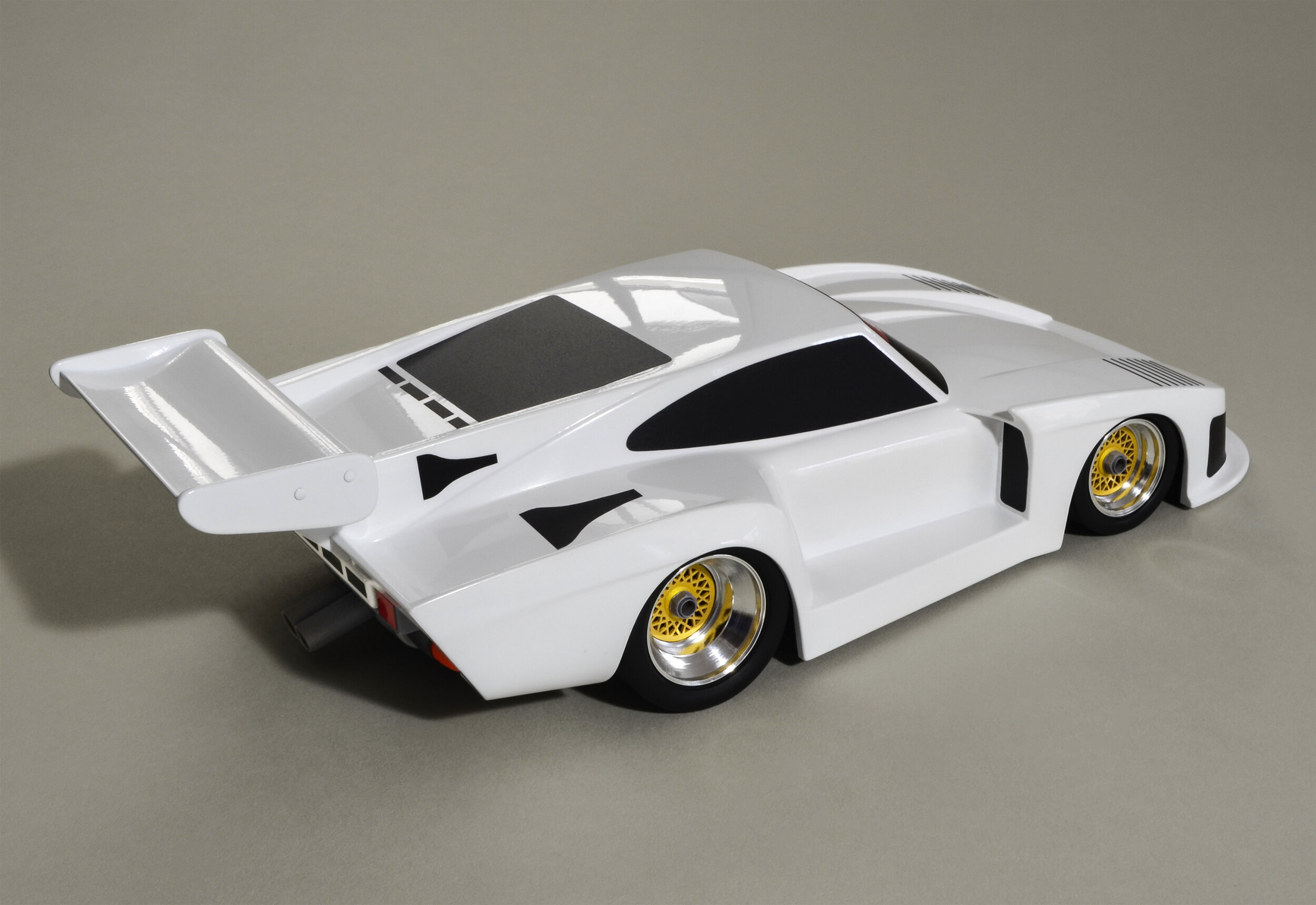
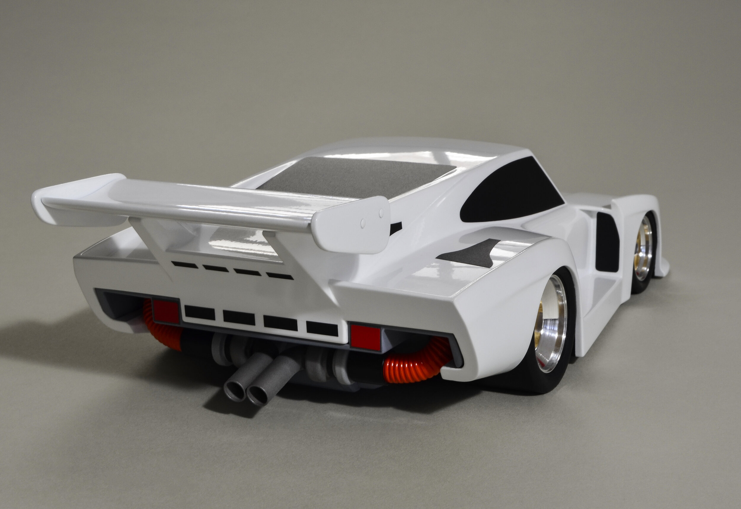
It's time for a set of relaxing walk-around images of the finished Co-Hog Porsche 935 artist's proof. Time to appreciate the changing highlights and reflections and how it sits, ready to scream out onto the track and send shivers up your spine - wailing and spitting flames with every downshift!

CoHogToys Finished Artist’s Proof

Finished Artist’s Proof

CoHogToys Overall length is about 16 1/2".

To give a sense of size I've included a one Euro coin and a US quarter.

The rear wheel diameter of the Co-Hog 935 is 1.08"/27.4mm. The US quarter is 0.95" and the Euro is 23 mm. Overall length is about 16 1/2".

Porsche 935 Artist’s Proof Final Steps & Assembly


The Porsche 935 Artist's Proof is almost done! It's taken about two years and two lifetimes of patience, but I can say that I'm really pleased with the way it has turned out.

The photos and descriptions will help catch up on some of what has been being done to finish the 935. It has been quite intense over the last month to make sure that everything came together correctly and in the right sequence. Major events included 2K clear-coating the body with subsequent wet-sanding and polishing. The engine was completely stripped down again and resized before repainting. The tires had to be stripped, sandblasted and repainted. Adding the graphics was its own major challenge and then it was assembly time.

Here the finished body and sub assemblies were ready for assembly - The red disk on the left is a fan wheel prototype that could be an option on future pieces. It's turned from aluminum and will have an aluminum hub an brass base and nut like those on the BBS style wheels.

004 10.jpg

Graphics were hand cut from car-wrapping vinyl. Some could be cut using meticulous measurements but many required creating acrylic templates. A few of those could be created from the CAD drawings, but the shapes of the most complicated ones had to be developed on the finished body to ensure a good fit.

The windshield was the most difficult to fit properly. The front lights and intake were challenging as well. The 3D compound curves made it tricky to cut the 2D piece to look right when applied. The yellow tape is quite thin so I applied it and then used thicker striping tape to develop the template shape. Once it was close, I traced the resulting boundaries, took off the guide tapes and had the right shape on the yellow tape to transfer to the acrylic blank. After several attempts and revisions the final template was ready. Every graphic piece had to be cut and applied at least twice and some took three or four times before they were just right.

005 10.jpg

The underside and wheel wells were masked off and coated with textured paint and then a flat finish. The three holes in a triangular pattern are for the jig plate dowel pins and the big hole in the center was for the large hand-held rod that allowed me to pivot and swivel the whole body as I painted it. The two rectangular holes are for the turbo intercooler lines (which I do realize are positioned incorrectly).

011 10.jpg

Once everything was painted, clear-coated and undercoated, the engine was too big to fit. It had to strip the paint, resize it and then refinish it all over again. Now I have a better idea of process flow and how to get good results the first time. Such is the value of an artist’s proof before making an edition.

008 10.jpg

Tires were finished and painted, but the surface was too smooth for the waterborne paint to properly adhere so the paint was stripped and the tires sandblasted - after making a sand blasting unit - and repainted. Several coats of flat clear finished them off nicely.

009 10.jpg

To add some attitude to go with the stance, all tires have 3 degrees of camber. It was important to make them the same so the whole thing would sit flat. CAD drawings were created to clarify and check the correct dimensions.

010 10.jpg

The added camber meant developing a mounting strategy to fit the tires into the tight wheel wells. The rears are particularly tight while the fronts needed 0.050" shims to position them in the wheel wells correctly.

Every square inch of this 935 Artist's Proof has been created, re-created and massaged several times over. I find it amazing to be able to say that, flaws and all, it is almost done. Thanks for following along on the ride

Porsche 935 Artist’s Proof Moves Into Painting


007 10.jpg

Joy and dismay came with the final 2K clear coats results. Joy that it came out so well. Dismay from seeing all the debris that would require days of sanding and polishing to remove. Wrinkled and worn out fingertips were part of the process, but it was wonderful to see it come to life under the lights.

002 Z-12-03-20-005 m1 c2.jpg

Primer coats beyond counting were applied and imperfections filled and sanded.

The two test bodies to the right were moved along one or two steps ahead of the 935 in order to do testing and develop techniques. Each was masked longitudinally so that I would have four halves to work with. At the end two old Co-Hog Special Edition blanks were enlisted for even more testing.

There were also multiple small assemblies made to simulate particularly tricky spots. It took lots of practice to be ready to spray the final color and clear coats.

003 Z-12-02-20-023 c1.jpg

This is the highly sophisticated warming booth (a large plastic bin on its end with a space heater at one end). All parts and assemblies were warmed and verified with a temp reader before spraying. The finishes were all heated as well.

004 002 c2.jpg

Four test blocks made from jelutong and basswood were tested with four body filler materials throughout the development process. Test dings and scratches were added to see how the wood/filler joints behaved as the finishes were applied. From past experience I knew there were many potential problems to be avoided. Additional filler types used during finishing also required ongoing testing.

Next steps were always tried on the test blocks first to find the best strategies for each situation.

005 Z-12-26-20-005 m1 c1.jpg

Another piece of highly sophisticated equipment - the drying booth. The engine bits and wheel laminations presented entirely different spraying challenges than the larger body parts.

006 c1.jpg

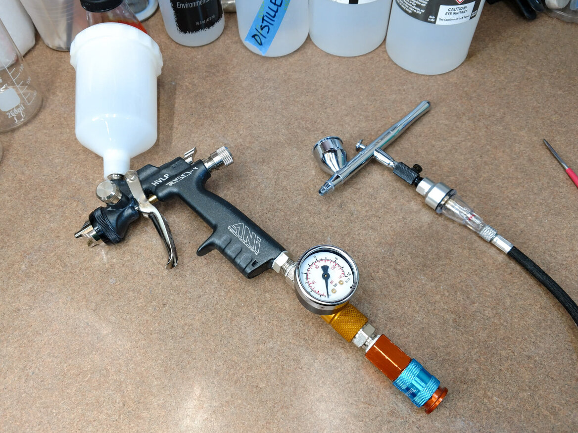
An Iwata LPH-80 (not shown) and an ANI R150-T mini-gun (compared to full-sized car spray guns) were used for the larger surfaces of the body.

An Iwata HP-CR3 airbrush was best for smaller pieces and getting into the corners , crevices and creases.

Spraying finishes is an art form that evolves from moment to moment as the temperature and humidity changes. The different paint materials all require slightly different mix ratios and pressure settings. It got complicated enough that note-taking was a regular part of every spraying session.

007 005 c1.jpg

The finishes being used are in general order of application from left to right:

- solvent-based shellac sealer - solvent-based automotive primer filler rattle cans - water- and solvent-based fillers and spot glazes - solvent-based automotive primer for mini-gun and airbrush - waterborne automotive sealers (these paints were semi-opaque so a base color was applied first) - waterborne automotive paints - colors, metallics and pearls - waterborne automotive clears - gloss and matte - reducers and cleaners - solvent-based rattle can decal carrier film

Not shown is the final solvent-based 2K clear coat. I was hoping to stay with waterborne throughout the process, but the quality was just not good enough. New products are always appearing and more testing will get me closer to the goal.

008 004 c1.jpg

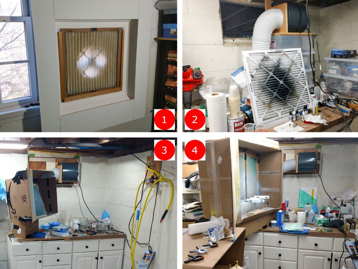
The spray booth itself is the final determinant in getting the best finish. Controlling the air flow and keeping the contaminants down are critical. My basement shop is not the best location for this, but gradual improvements have been made and more are in the works. I have a 4’ Binks booth with an 18” fan that I used for the early Co-Hogs, but it would suck everything in the house through the window! Smaller is better in this case and quality control will have to evolve.

A brief development chronology:

1 - January 2020 - 8" fan in a bedroom window - only small parts

2 - July 2020 - 6" fan and ducting in cellar window - still small parts

3 - October 2020 - same fan and ducting with window sealed for coming winter weather - cardboard box enclosure needed to contain overspray from mini-gun used for complete body coverage

4 - December 2020 - same fan and ducting - even bigger box enclosure - first so-called drying booth

Plans for an enclosed booth with an explosion-proof 10" fan and proper filtering are well along and parts are being gathered.